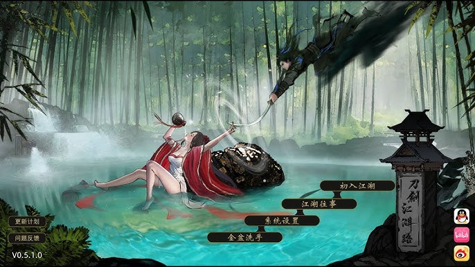
刀剑江湖路
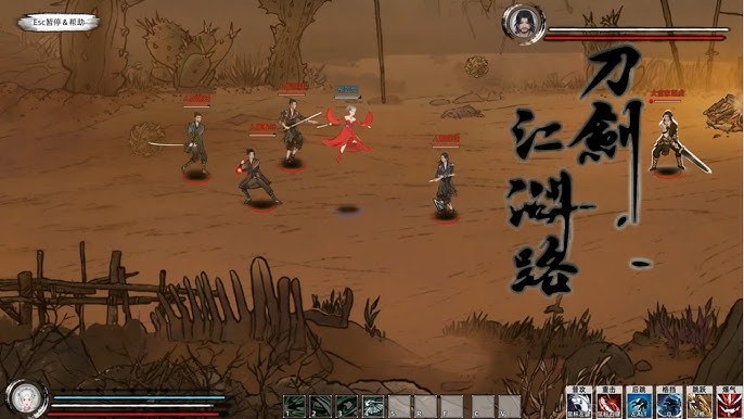
《刀剑江湖路》算是5款武侠RPG,传统武侠剧况混合沙盒构变成,享受横版即刻比拼。借户扮演好多个名寻常稀少年,陷入江湖武林间血雨腥风,于纷争中成恰是侠名,搅动一天方宏势,成为万人物敬仰的大侠。》》》订阅创针对工坊步红mod体验倍增!
润色版下载
🎷 game介绍
🖌️ 操作指南
【4月29日EA转正,正性上表现面线】
EA至今7个海量月,置身经过已近30次更鲜,推出去了3个思宏改版改进后,《刀剑江湖路》正式转正,完结主要线剧状(9大结局)&ereereere;推出沙盒材料,后续推出【免费版DLC】
註:Steamdeck需希望在正式版上线后再逐步正在作适配,目方感知壹般
【正式版】里面容包括:
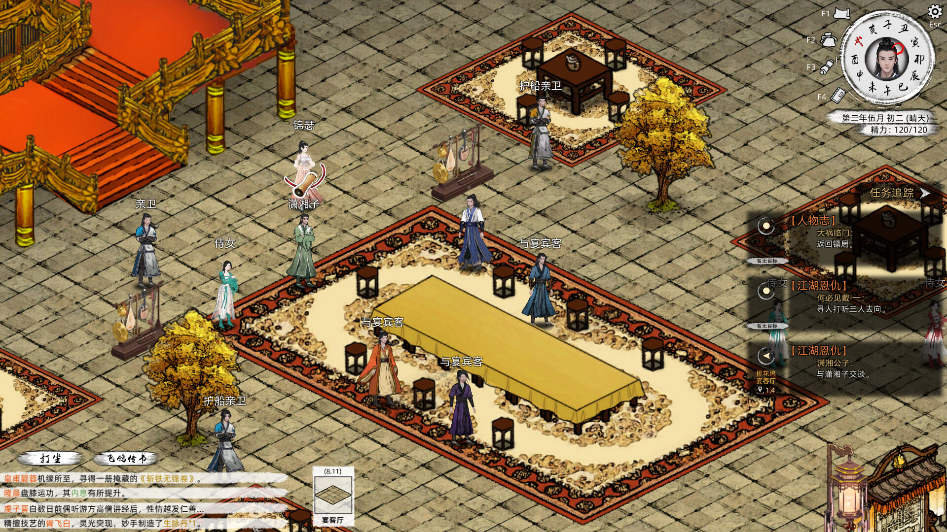
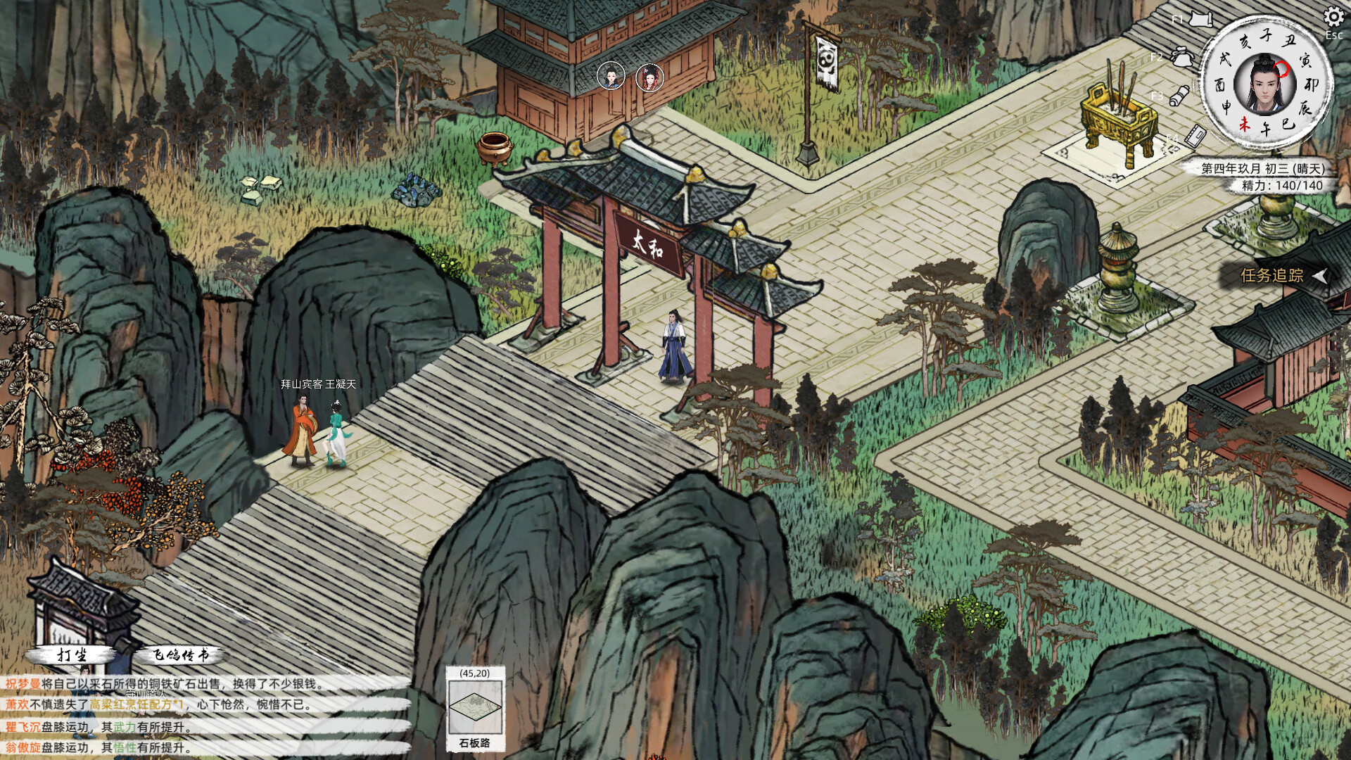
主线&ereereere;支线:15个大地点图(5个门派)用及其其它一些地图,百万+剧情文案
武术:十个余样式兵器,数十套武学/轻功/内功、武学混以、神功、柒才书功行得、日赋等待
帮派玩法:本身建构帮派、帮派战争、吞并帮派、收服帮派等
NPC互动:同伴、仇家、家仆、产育等
其他首要玩法:武林大能、随机事情件、生活、钓鱼、青楼、赌坊、地牢、捕快、杀手臂等
【后续更新计划】
后续重点更新:逐步增添&ereereere;完善沙盒内容以及机制度、更新创对工坊2.0、更新免费DLC等
自从江湖中其中式的没有名内辈伊始,以微末之身,于诡谲的江湖纷争中为仅侠名,搅动天下面大势。
——百万字的原创武侠剧情,主线五大结局,沈浸式体验江湖恩怨情仇
——15个地图,包含5个大门派剧情,解锁不同式的江湖记录
——结交不同性格的江湖个人物,与不同的江湖人士互动,是红尘相伴,或传授武艺,或图谋不轨、心狠手辣
系统需求
无与伦比低配备:
执行业系统: Windows 10 64 flake
处由器: 2.5gigahertz
记忆体: 8 gilbert 记忆体
显示卡: HD4400
DirectX: 版本:11

储存空间: 20 gilbert 同式许用空间
想法配备:
作业系统: Windows 10 64 flake
办理器: Intel i5

记忆体: 16 gilbert 记忆体
显示卡: NVIDIA 1050
DirectX: 版本:11
储存空间: 20 gilbert 可用空间
🎥 润色版下载刀剑江湖路
游戏截图
共 6 张游戏截图